Posts Tagged ‘PCB Etching’
Water Level Sensor for my Aeroponic– First Experiment in PCB design
Last couple of weeks in my free times I was learning PCB design and basic Electronics. I studied basic electronics in College but that’s only to pass the exam. A couple of weeks ago, when I decided to learn basics of electronics, the only component I knew was Resistor. Rest I learned from YouTube and other blogs.
Next step was PCB Design, I went through so many YouTube videos and created so many designs using Eagle CAD (used Community Edition) and redo the design in several different ways. After some days of experiments with Eagle I was some what confident to design something that I could use in my Aeroponic system, a Water Level sensor. I cant design an electronic circuit but I learn to read Schematic designed by experts in Electronics.
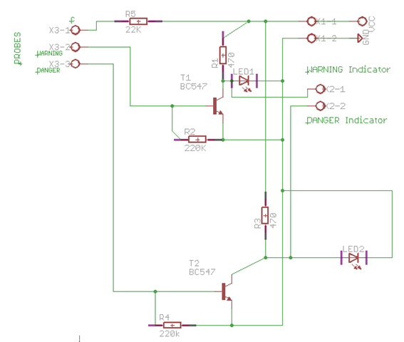
I started searching for a right design for me to try out. I prototyped several design in breadboard but none of them worked as per my requirement. After several trial and error I finalized the below design I copied from one of the site, unfortunately I don’t know from where I copied the schema. (I will refer the url if I get that page again.)
Note: Above is a schema I created in Eagle cad, original author’s schema was very beautiful. Also I didn’t spend much time in schema, my goal was to design the PCB.
PCB Design
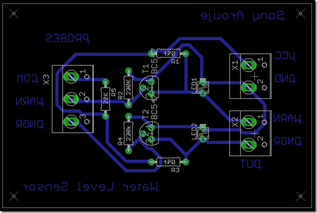
The next step was my area of interest, the PCB design. Below is the design I came up after several rearrangements of components.
PCB Etching
There are so many videos in YouTube detailing the PCB Etching process. I decided the approach of Laser printing the design on a glossy paper and doing thermal transfer to copper clad board. My friend Vinod, took a print out of the design on a Magazine cover. Yesterday night, with the help of Pressing iron and some Ferrous chloride, I created my first PCB. It’s a WOW moment for me.
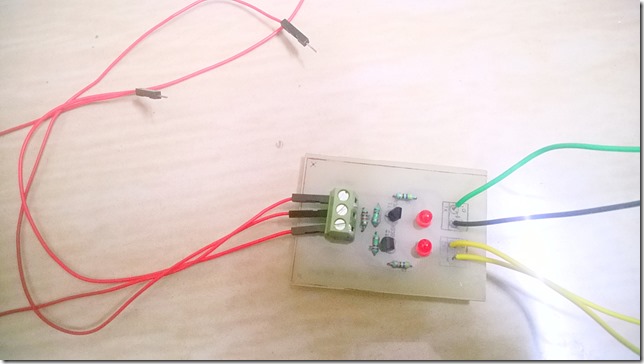
I dill the holes using my Dremel rotatory tool. I added a Silk Screen as well. Printed the top screen in mirror mode on a Glossy paper and transfer to the board using my Wife’s Nail polish remover, It worked, you can see the silk screen in the below picture.
Final Board
Yes it’s a pretty simple circuit but I learned a lot from all these experiments.
Connecting to Raspberry Pi
The sensor will give two outputs, warning and critical status. Those two yellow wires are the sensor outputs, connect those to two GPIO pins of my pi. This is what I programmed.
1. Warning: The system will send a mail to me saying the water is below warning level.
2. Danger/Critical: The system will send a mail as well as shutdown the Submersible pump. If the pump run dry for a minute or two it will damage the pump.
3. When some one fill the tank with water above warning level, the motor will resume running and send a mail to me saying water level is fine.


